When You've Changed One Too Many Wheel Bearings with Hand Tools...
My colleague’s car didn’t pass the inspection due to a worn-out wheel bearing. Like a true engineer, he wanted to change the bearing himself. However, he had done the process one too many times in his home garage the good ol’ traditional way (hammering the bearing until your hands go numb). Therefore, he wanted to get a hydraulic press for the job. Buying one would have of course been far too simple, so we did the only rational thing and started to build one ourselves! Basic design of the press was adopted from an existing DIY project online. One extremely helpful technician colleague of ours also gave us a bunch of tricks and tips for the manufacturing process.
Materials and Parts
For the actual pressing part of the machine, we bought a cheap 8 ton bottle jack. To figure out a suitable material and shape for the frame, we created a basic CAD model of the frame and ran some FEM simulations with stress analysis corresponding to the full load of the 8 ton jack. After some iterations we came to the conclusion that we can create the frame quite effortlessly from 40x40x3 mm RHS structural steel S355. In the simulation, this design was subject to maximum stress regions of slightly over 300 MPa, so there wasn’t exactly much of a safety margin. However, we made the “educated” guess that slight plastic deformations might not critically weaken the design, as the press will realistically be used so little that it shouldn’t experience any fatigue. After all, there are only so many occasions in your life when you need to change a wheel bearing… I guess time will tell whether we were too bold in our assumptions.
Manufacturing Process
Overall manufacturing the frame was quite simple. First we spent quite a good while cutting the RHS tube to pieces of correct lengths with a band saw. After that we drilled the necessary holes, positioning them ridiculously accurately with a manual milling machine. For the slider, which keeps the bottle jack in correct orientation when moving up and down, we took some 5x40 mm flat steel bar which we bent with a press brake to the appropriate shape. We also added some plastic pieces to the slider to prevent steel-on-steel contact.
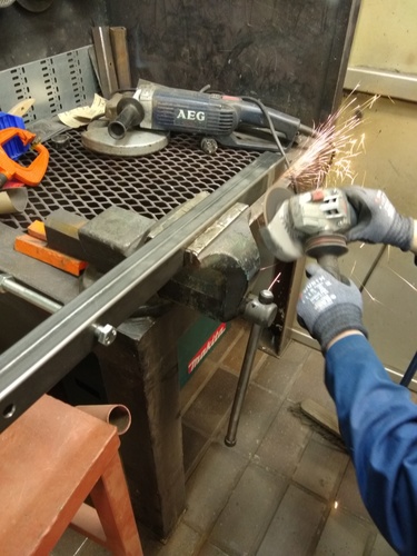
Then it was time to do some serious welding. Well, actually we did do some grinding before the welding, as we wanted to make sure the welded surfaces were clean of any dirt and oil.
We started the welding by assembling the core pieces together with magnets and clamps, and welding them together with small spots from the corners. After making sure the pieces were sitting correctly, we continued to add parts to the assembly. When everything was sitting nicely together with the small corner welds, we started welding the actual seams. We welded each seam in a symmetrical order, always repeating the same seam on the other side of the assembly. This was done to counter as much of the bending caused by material transformation as possible.
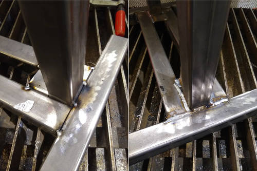
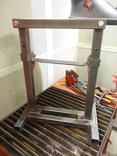
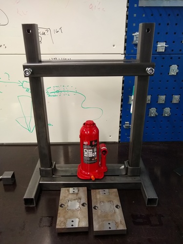
As an end result, we had a working frame for the hydraulic press. The whole design was still quite far from finished, the bottle jack still needs to be attached and some springs need to be added to hold the jack up. Most importantly, a good layer of paint must be added to the frame to hide some of the more unsuccessful weld seams… Anyway, we still got to break something with the press, and that’s all that matters.